| Set | FDUA100AVNPWVH | FDUA100AVNAWVH | FDUA125VNPWVH | FDUA125AVNPWVH | FDUA125AVNXWVH | FDUA140AVNXWVH | FDUA160AVNXWVH | | Set | FDUA100AVSAWVH | FDUA125AVSXWVH | FDUA140AVSXWVH | FDUA160AVSAWVH | FDUA200AVSAWVH | FDUA250AVSAWVH |
| Indoor | FDUA100VH | FDUA100VH | FDUA125VH | FDUA125VH | FDUA125VH | FDUA140VH | FDUA160VH | | Indoor | FDUA100VH | FDUA125VH | FDUA140VH | FDUA160VH | FDUA200VH | FDUA250VH |
| Outdoor | FDCA100VNP-W | FDCA100VNA-W | FDC125VNP-W | FDCA125VNP-W | FDCA125VNX-W | FDCA140VNX-W | FDCA160VNX-W | | Outdoor | FDCA100VSA-W | FDCA125VSX-W | FDCA140VSX-W | FDCA160VSA-W | FDCA200VSA-W | FDCA250VSA-W |
| Power source (Outdoor Unit) | | 1 Phase 240V 50Hz | | | Power source (Outdoor Unit) | | 3 Phase 380-415V 50Hz |
| *Operation data | Nominal Capacity (Range) | Cooling T1 | kW | 10 (2.1 -10.2) | 10.0 (4.0-11.2) | 12.1 (5.0-12.1) | 12.1 (5.0-12.1) | 12.5 (5.0-14.0) | 14.0 (5.0-14.5) | 16.0 (5.0-17.0) | | *Operation data | Nominal Capacity (Range) | Cooling T1 | kW | 10.0 (4.0-11.2) | 12.5 (5.0-14.0) | 14.0 (5.0-14.5) | 16.0 (6.9-20.0) | 20.0 (6.9-28.0) | 23.5 [ 6.9(Min.) - 28.0(Max.)] |
| Heating H1 | 10 (1.7 - 10.4) | 11.2 (4.0-12.5) | 12.1 (4.0-13.3) | 12.1 (4.0-13.3) | 14.0 (4.0-17.0) | 16.0 (4.0-18.0) | 18.0 (4.0-21.0) | | Heating H1 | 11.2 (4.0-12.5) | 14.0 (4.0-18.0) | 16.0 (4.0-18.0) | 18.0 (5.5-22.4) | 22.4(5.5-31.5) | 28.0 [ 5.5(Min.) - 31.5(Max.)] |
| Heating H2 | 7.6 | 10 | 7.9 | 7.9 | 14.2 | 15.5 | 15 | | Heating H2 | 10 | 14.2 | 15.5 | 16.1 | 21 | 21.1 |
| Power consumption | Cooling T1 | kW | 2.99 | 3.05 | 3.85 | 3.85 | 3.83 | 4.02 | 5 | | Power consumption | Cooling T1 | kW | 3.05 | 3.83 | 4.02 | 4.68 | 5.78 | 7.7 |
| Heating H1 | 2.57 | 2.87 | 3.28 | 3.28 | 3.68 | 4.19 | 5 | | Heating H1 | 2.87 | 3.68 | 4.19 | 4.6 | 5.44 | 7.7 |
| Maximum power consumption | kW | 4.46 | 6.4 | 4.75 | 4.75 | 6.13 | 5.77 | 7.1 | | Maximum power consumption | kW | 10.2 | 7.66 | 7.26 | 11.2 | 11.2 | 11.2 |
| Running current | Cooling T1 | A | 13.2 | 14.7 | 16.2 | 16.2 | 17 | 17.8 | 22 | | Running current | Cooling T1 | A | 4.7 | 6.4 | 6.7 | 7.5 | 9.1 | 12 |
| Heating H1 | 11.4 | 14 | 13.8 | 13.8 | 16.3 | 18.6 | 22 | | Heating H1 | 4.4 | 6.2 | 6.9 | 7.5 | 8.6 | 12 |
| Inrush current, maximum current | | A | 5, 19 | 5, 26 | 5, 20 | 5, 20 | 5, 29 | 5, 30 | 5, 30 | | Inrush current, maximum current | A | 5, 17 | 5, 18 | 5, 19 | 5, 24 | 5, 27 | 5, 27 |
| EER | Cooling T1 | | 3.34 | 3.28 | 3.14 | 3.14 | 3.26 | 3.48 | 3.16 | | EER | Cooling T1 | | 3.28 | 3.26 | 3.48 | 3.42 | 3.46 | 3.16 |
| COP | Heating H1 | 3.89 | 3.9 | 3.69 | 3.69 | 3.8 | 3.82 | 3.6 | | COP | Heating H1 | 3.9 | 3.8 | 3.82 | 3.91 | 4.12 | 3.67 |
| Sound power level (JIS C9612) | Outdoor | dB(A) | 68 | 69 | 73 | 73 | 68 | 69 | 69 | | Sound power level (JIS C9612) | Outdoor | dB(A) | 69 | 68 | 69 | 73 | 73 | 73 |
| Sound pressure level (JIS C9612) | Indoor | dB (A) | P-Hi:43 Hi:42 Me:40 Lo:37 | P-Hi:43 Hi:42 Me:40 Lo:37 | P-Hi:46 Hi:44 Me:42 Lo:38 | P-Hi:46 Hi:44 Me:42 Lo:38 | P-Hi:46 Hi:44 Me:42 Lo:38 | P-Hi:48 Hi:47 Me:43 Lo:38 | P-Hi : 48 Hi : 47 Me : 43 Lo : 41 | | Sound pressure level (JIS C9612) | Indoor | dB (A) | P-Hi:43 Hi:42 Me:40 Lo:37 | P-Hi:46 Hi:44 Me:42 Lo:38 | P-Hi:48 Hi:47 Me:43 Lo:38 | P-Hi:48 Hi:47 Me:43 Lo:41 | P-Hi:52 Hi:50 Me:47 Lo:45 | P-Hi : 52 Hi : 50 Me : 47 Lo : 45 |
| Outdoor | 56 | 55 | 57 | 57 | 54 | 54 | 54 | | Outdoor | 55 | 54 | 54 | 58 | 58 | 58 |
| External dimensions (HxWxD) | Indoor | mm | 398x1150(+86)x650 | 398x1150(+86)x650 | 398x1150(+86)x650 | 398x1150(+86)x650 | 398x1150(+86)x650 | 398x1450(+86)x930 | 398x1450(+86)x930 | | External dimensions (HxWxD) | Indoor | mm | 398x1150(+86)x650 | 398x1150(+86)x650 | 398x1450x930 | 398x1450x930 | 379x1600(+85)x893 | 379x1600(+85)x893 |
| Outdoor | 750 × 880(+88) × 340 | 845x970x370 | 845x970x370 | 845x970x370 | 1300x970x370 | 1300x970x370 | 1300 × 970 × 370 | | Outdoor | 845x970x370 | 1300x970x370 | 1300x970x370 | 1505x970x370 | 1505x970x370 | 1505x970x370 |
| Net weight | Indoor | kg | 52 | 52 | 52 | 52 | 52 | 66 | 66 | | Net weight | Indoor | kg | 54 | 52 | 66 | 66 | 88 | 88 |
| Outdoor | 57 | 77 | 73 | 73 | 97 | 97 | 97 | | Outdoor | 78 | 99 | 99 | 145 | 145 | 145 |
| Supply air connection | mm | 348x898 | 348x898 | 348x898 | 348x898 | 348x898 | 298x1064 | 298x1064 | | Supply air connection | mm | 348x898 | 348x898 | 298x1064 | 298x1064 | 250x1450 | 250x1450 |
| Return air connection | mm | 348x898 | 348x898 | 348x898 | 348x898 | 348x898 | 2 X φ400 | 2 X φ400 | | Return air connection | mm | 348x898 | 348x898 | 2 X φ400 | 2 X φ400 | 250x1450 | 250x1450 |
| External Static Pressure (max) | Pa | 200 | 200 | 200 | 200 | 200 | 150 | 150 | | External Static Pressure (max) | Pa | 200 | 200 | 150 | 150 | 200 | 200 |
| Airflow | Indoor (Cooling) | l/s | P-Hi:650 Hi:600 Me:550 Lo:483 | P-Hi:650 Hi:600 Me:550 Lo:483 | P-Hi:717 Hi:650 Me:600 Lo:500 | P-Hi:717 Hi:650 Me:600 Lo:500 | P-Hi:717 Hi:650 Me:600 Lo:500 | P-Hi:1000 Hi:867 Me:733 Lo:600 | P-Hi : 1000 Hi : 867 Me : 733 Lo : 683 | | Airflow | Indoor (Cooling) | l/s | P-Hi:650 Hi:600 Me:550 Lo:483 | P-Hi:717 Hi:650 Me:600 Lo:500 | P-Hi:1000 Hi:867 Me:733 Lo:600 | P-Hi:1000 Hi:866 Me:733 Lo:683 | P-Hi:1333 Hi:1200 Me:1067 Lo:933 | P-Hi:1333 Hi:1200 Me:1067 Lo:933 |
| Indoor (Heating) | P-Hi : 1000 Hi : 867 Me : 733 Lo : 600 | | Indoor (Heating) | P-Hi:1000 Hi:866 Me:733 Lo:600 |
| Refrigerant (R32) | Quantity | kg | 1.7 | 3.3 | 2.25 | 2.25 | 4 | 4 | 4 | | Refrigerant (R32) | Quantity | kg | 3.3 | 4 | 4 | 5.1 | 5.1 | 5.1 |
Pre charged to pipe length | m | 15 | 30 | 15 | 15 | 30 | 30 | 30 | | Pre charged to pipe length | m | 30 | 30 | 30 | 30 | 30 | 30 |
| Installation data | Refrigerant piping | Liquid line | mm | **Ø6.35 | **Ø6.35 | Ø9.52 | Ø9.52 | Ø9.52 | Ø9.52 | Ø9.52 | | Installation data | Refrigerant piping | Liquid line | mm | Ø9.52 | Ø9.52 | Ø9.52 | Ø12.7 | Ø12.7 | Ø12.7 |
| Gas line | Ø15.88 | Ø15.88 | Ø15.88 | Ø15.88 | Ø15.88 | Ø15.88 | Ø15.88 | | Gas line | Ø15.88 | Ø15.88 | Ø15.88 | Ø22.22 , Ø25.4 or Ø28.58 | Ø22.22 , Ø25.4 or Ø28.58 | Ø22.22 , Ø25.4 or Ø28.58 |
| Connection method | | Flare Connection | | Connection method | | Flare Connection | Liquid : Flare / Gas : Brazing |
| Maximum pipe (one way) length | m | 30 | 50 | 30 | 30 | 100 | 100 | 100 | | Maximum pipe (one way) length | m | 50 | 100 | 100 | **70 | **70 | **70 |
| Max vertical height diff. between O.U. and I.U. | m | 20 ( O.U. above I.U. ) / 20 ( O.U. below I.U. ) | 50 ( O.U. above I.U. ) / 15 ( O.U. below I.U. ) | 20 ( O.U. above I.U. ) / 20 ( O.U. below I.U. ) | 30 ( O.U. above I.U. ) / 15 ( O.U. below I.U. ) | ***50 ( O.U. above I.U. ) / 15 ( O.U. below I.U. ) | | Max vertical height diff. between O.U. and I.U. | m | 50 ( O.U. above I.U. ) / 15 ( O.U. below I.U. ) | 30 ( O.U. above I.U. ) / 15 ( O.U. below I.U. ) | ***50 ( O.U. above I.U. ) / 15 ( O.U. below I.U. ) |
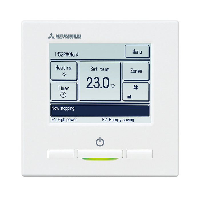
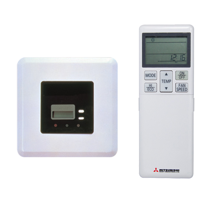
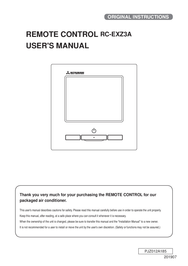
| Controller | RC-E5, RC-EXZ3A, RCH-E3 or RCN-KIT4-E2 | | Controller | RC-E5, RC-EXZ3A, RCH-E3 or RCN-KIT4-E2 |
| Safety Pan (Optional) | UA-SP2-E (Optional) | UA-SP2-E (Optional) | UA-SP2-E (Optional) | UA-SP2-E (Optional) | UA-SP2-E (Optional) | NA | NA | | Safety pan (Optional) | UA-SP2-E (Optional) | NA | NA | NA | NA |
| Motion Sensor (Optional) | LB-KIT2 | | Motion Sensor (Optional) | LB-KIT2 |
| Demand response (AS4755) | No | Yes | No | Yes | Yes | Yes | Yes | | Demand response (AS4755) | Yes | Yes | Yes | Yes | Yes | Yes |
| Outdoor air temperature (upper, lower limits) | Cooling | C | -15 to 46 | -15 to 50 | -15 to 46 | -15 to 46 | -15 to 50 | -15 to 50 | -15 to 50 | | Outdoor air temperature (upper, lower limits) | Cooling | C | -15 to 50 | -15 to 50 | -15 to 50 | -15 to 50 | -15 to 50 | -15 to 50 |
| Heating | C | -15 to 20 | -20 to 20 | -15 to 20 | -15 to 20 | -20 to 20 | -20 to 20 | -20 to 20 | | Heating | C | -20 to 20 | -20 to 20 | -20 to 20 | -20 to 20 | -20 to 20 | -20 to 20 |
| | | | | | | | | | | | | | | | | | | | | |
| * Operation data are are conducted in accordance with AS/NZS 3823 standard. For testing conditions please refer to Page xxx | | | | | | | | * Operation data are conducted in accordance with AS/NZS 3823 standard. For testing conditions please refer to Pagexxx | | | |
| | | | | | | | | |
| **Reducer set Ø9.52 --> Ø6.35 is included in the outdoor unit as accessory for FDCA100VNP-W. | | | | | | | | ** Maximum 70m(Gas piping:φ25.4 or φ28.58), Maximum 35m(Gas piping:φ22.22) | | | | | | |
***Max.30m (Outdoor unit is higher & Outdoor air temperature > 43˚C) | | | | | | | | | | | | *** Max.30m (Outdoor unit is higher & Outdoor air temperature > 43˚C) | | | | | | |
